When building a network for communication between a large number of devices, one may think: what interface to choose? Each interface has its own pros and cons that determine its application: CAN — Automotive, RS485 / RS232 — Industrial, Ethernet — Consumer Electronics / Server. What features of the transceiver microcircuit help to protect against many problems during installation and operation? How is the process of measuring and researching of transceiver microcircuits going on? New RS485 microcircuit is ready to get to market!
RS485 — what is it?
So, before talking about the microcircuit itself, we need to figure out what does the data transfer standard represent itself.

In RS-485, twisted pair is used to transmit and receive data. Data transmission is carried out using differential signals, which in turn provides high resistance to common mode noise. A voltage difference of one polarity means a logical 1, a difference of the other polarity means a logical 0.

Common Mode Noise Resistance
Common mode noise resistance is a very important property for this type of transceiver — when many devices are connected to the network, voltage spikes are very common.
In practice, to implement the RS485 topology, transceiver microcircuits are needed. In this case, of course, the characteristics of the microcircuit must fully comply with the requirements of the standard.
In the RS485 interface, when organizing a network, a microcircuit that transmits information is called Master, and the one that receives information — Slave. The maximum number of devices in a line can be 256.
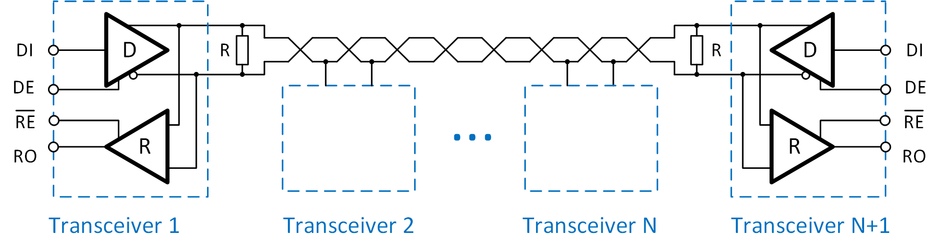
Typical application diagram of RS485 transceiver microcircuits
In order to create an RS485-based network for microcontrollers, an additional transceiver microcircuit must be used. The microcontroller connects to it via the UART protocol after which the transceiver starts broadcasting.

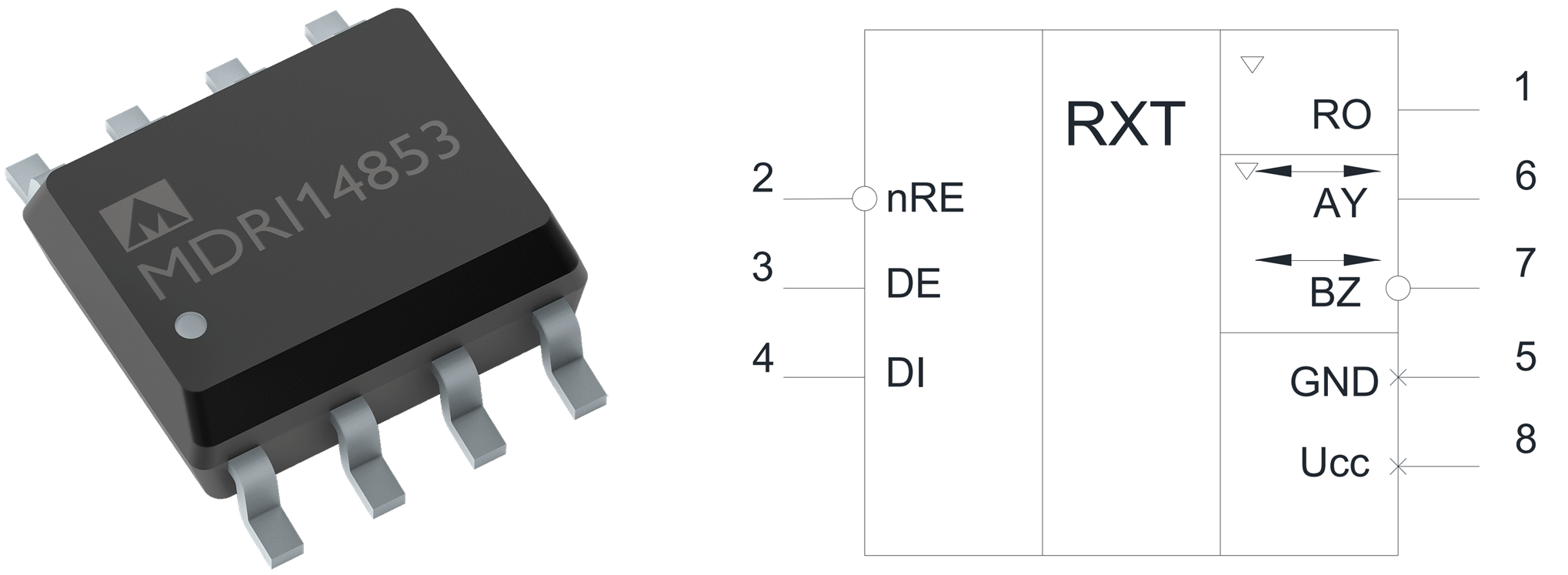
New generation of RS485 transceiver: MDRI14853SI
We have already been serially releasing the K5559IN10BSI microcircuit, but taking into account how quickly the amount of data transmitted by controllers grows, 2.5Mbit speed is not enough. Therefore, further on, we will examine our new MDRI14853SI microcircuit — now 30 Mbit.
The die turned out to be quite small (1.3mm * 1.3mm), which allows us to compete in price with the main world players on the market:
Let's compare the main characteristics of the MDRI14853SI with foreign analogs.
Parameters comparison
| Parameter | MDRI14853SI | MAX14783EEUA | ST3485EB | ADM3490E | THVD14xx |
| Power supply | 3,0–5,5 V | 3,0–5,5 V | 3–3,6 V | 3–3,6 V | 3,0–5,5 V |
| Data transfer rate (max.) | 30 Mbit/s | 30 Mbit/s | 15 Mbit/s | 12 Mbit/s | 50 Mbit/s |
| Current consumption | 1,4 (max. 2) mA | 1,9 (max. 4) mA | 1,3 (max. 2,2) mA | 1,1 (max. 2,2) mA | 2,4 (max. 3) mA |
| Current consumption in «Power Down» mode | <2 uA | <10 uA | <1 uA | <10 uA | <1 uA |
| Leakage current on terminals AY, BZ | –100...125 uA | –800...1000 uA | –800...1000 uA | –800...1000 uA | -100...125 uA |
| Receiver input impedance | 96 kOm | 12 kOm | 24 kOm | 12 kOm | 96 kOm |
| Differential output voltage | >1,5 V | >1,5 V | >1,5 V | >1,5 V | >1,5 V |
| Receiver switching threshold | –0,210…–0,030 V | –0,200…–0,010 V | –0,200…–0,010 V | –0,200…–0,010 V | -0,25…-0,05 V |
| Transmitter propagation delay | 25 ns | 20 ns | 30 ns | 35 ns | 20 ns |
| Transmitter turn-on time (Reciever on) | 60 ns | 30 ns | 50 ns | 90 ns | 50 ns |
| Transmitter turn-on time (Reciever on off) | 10 us | 6 us | 0,05 us | 0,9 us | 6 us |
The parameters turned out to be comparable with the foreign analogs, which is good news for the developers of the microcircuit. However, achieving good performance is only the tip of the iceberg. Let's try to look more detailed inside of the microcircuit. Regardless of what is described in the standard, any microcircuit has its own «features». Let's have a look at some of them and open the door into the world of the research process.
Short circuit protection
When organizing networks based on RS485, a situation is possible when the transmitter «broadcasts» to a line in which another potential is consistently present. Most often, this situation occurs when two or more transmitters are “broadcasting” simultaneously. What will happen to the transmitter microcircuits in this connection? In principle, nothing good. Let's have a look at a simple example. Let's connect two transmitters directly (we take only one connection for a twisted pair, for the other everything will be the same, but with inversion): at the output of transmitter 1 there will be a potential of + 5V (power supply), at the output of transmitter 2 there will be 0 (Ground).

Transistors P1 and N2 will be open, and without additional protection, a short-circuit current will flow through them, which will be limited only by insignificant resistances of the transistors themselves and the conductor. Most often, in such a situation, there is only one outcome — thermal breakdown of transistors.

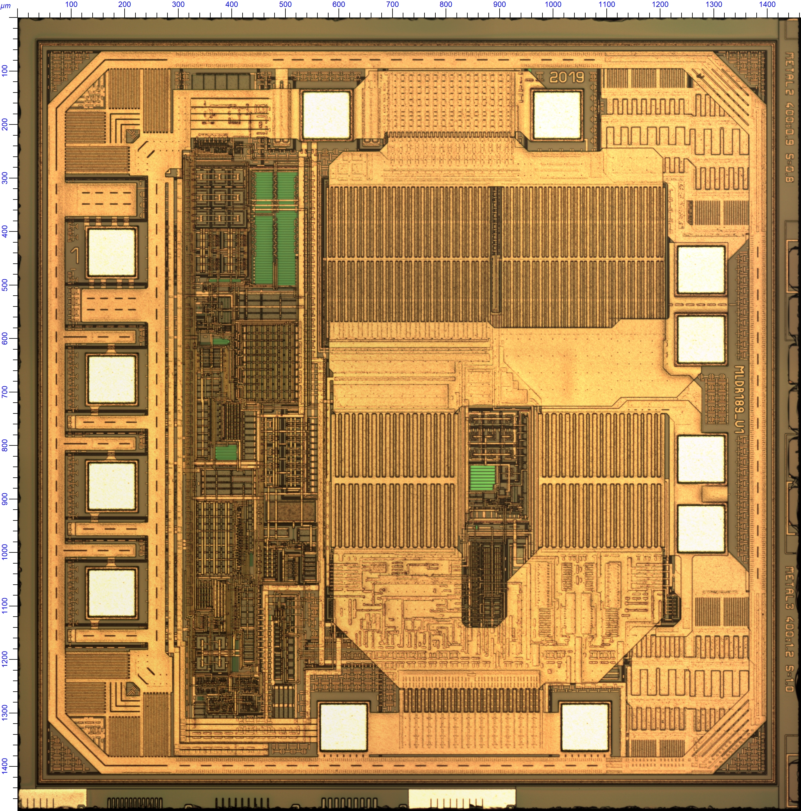
The corner fragment of a die (chip) photo of an RS485 microcircuit of an unsuccessful revision.
According to the RS485 standard, the voltage in the line can be from -7 Volts to +12 V (this is due to the fact that the pads of the microcircuits can be at a fairly decent distance from each other, more than one kilometer, and scatter relative to each other). The worst situation, that is, the maximum short-circuit currents can be in the case when the transmitter broadcasts a «logical unit», and the potential of -7 V is consistent in the line, and the second situation is when the transmitter broadcasts a logical 0, and the potential of 12 V is consistent in the line.
The easiest way to protect the microcircuit from short-circuits is to add limiting resistors for each transistor in the output buffer. The bottom line is this: we add resistors to the system when the current in them is growing, according to Ohm's law —
 – the voltage across the resistor begins to rise. When
  becomes equal to the threshold of the transistor (on the picture below Pfb and Nfb), becomes equal to the threshold of the transistor actuation (in the picture below Pfb and Nfb), feedback is turned on, and the short-circuit current goes into saturation. In one revision we did just like that, but it turned out to be a fail…
Due to the fact that the voltage in the circuit can be higher than the power supply, a reverse current occurs. If the system has been powered by an external source, it could suppress this voltage, but it was powered by an internal LDO (linear voltage regulator). The reverse current raised the LDO voltage and the circuit burned out. The solution that we came up with is as follows:

The reference current sources set the current through transistors N3 and P3. The circuit of current mirror determines the maximum current that can pass through the N2 and P2 transistors, thereby limiting both — the forward short-circuit current and the reverse. The solution turned out to be workable in terms of simulation, now we have to test it in hardware.
Let's move on to measurements. We need a power supply: a precise Keithley2602A source-meter and software that allows one to control the source-meter and take VAC (volte-ampere characteristics). For measurements automation, our application engineers have developed a matrix switcher that allows one to automatically switch the source-meter to different pins of the microcircuit. We use LabView to communicate with the devices.

We will examine the switch separately, there are foreign analogs, of course, but this particular 64x8 switch — the development of our engineering team, was made with a focus on its daily tasks. It allows switching 64 outputs of the microcircuit for 8 channels (to which you can connect any equipment), eliminating the manual work before each measurement.
And of course, the measuring device itself:

Overall, we get the following VA (Volt-Ampere-Characteristics) for the transmitter output:

From the VA characteristic, we see the following: in the worst cases, with stable potentials of -7 V or 12 V in line, the current of the microcircuit is limited to 90 mA.
The transistors of the microcircuit are not destroyed during a short circuit (at a potential in the line)! Short circuit protection works – retrieved.
However, if you hold it in the short circuit mode for some time (about 2 minutes), then the next «feature» will work — thermal protection and the circuit will turn off.
Internal thermal protection
Overheating protection is built into almost all foreign RS485 transceiver microcircuits and is an integral functional part of the circuit. At elevated temperatures, the parameters of the transistors begin to degrade, and with a short-circuit current, heating is inevitable and, therefore, it is important to turn the microcircuit off in time.
The situation with overheating is aggravated by the plastic case, which poorly dissipates the heat. The topology of the die also has undergone serious optimization in order to accommodate the maximum functionality on the minimum area. If we draw an analogy with the real world, then a plastic case for a die is like a down jacket for a person.
The guaranteed temperature range, in which the microcircuit should function: –40…+85 °С.
In K5559IN86ASI, the thermo-sensor response threshold is located around 165 ºС — when this value is reached, the microcircuit will turn off. But this is about the temperature of the die, not the case, the figure of 165 ºС is also not accidental: at this temperature the die will not be damaged at all and will continue to function after cooling. The operating temperature range, stated in the documentation, is given relative to the ambient temperature, and, fairly speaking, it is easier to control.
The testing of the microcircuit operation in different temperature range was checked using the SU-262 heat and cold test chamber. The chamber allows you to set the temperature from –60 ° С to 150 ° С.
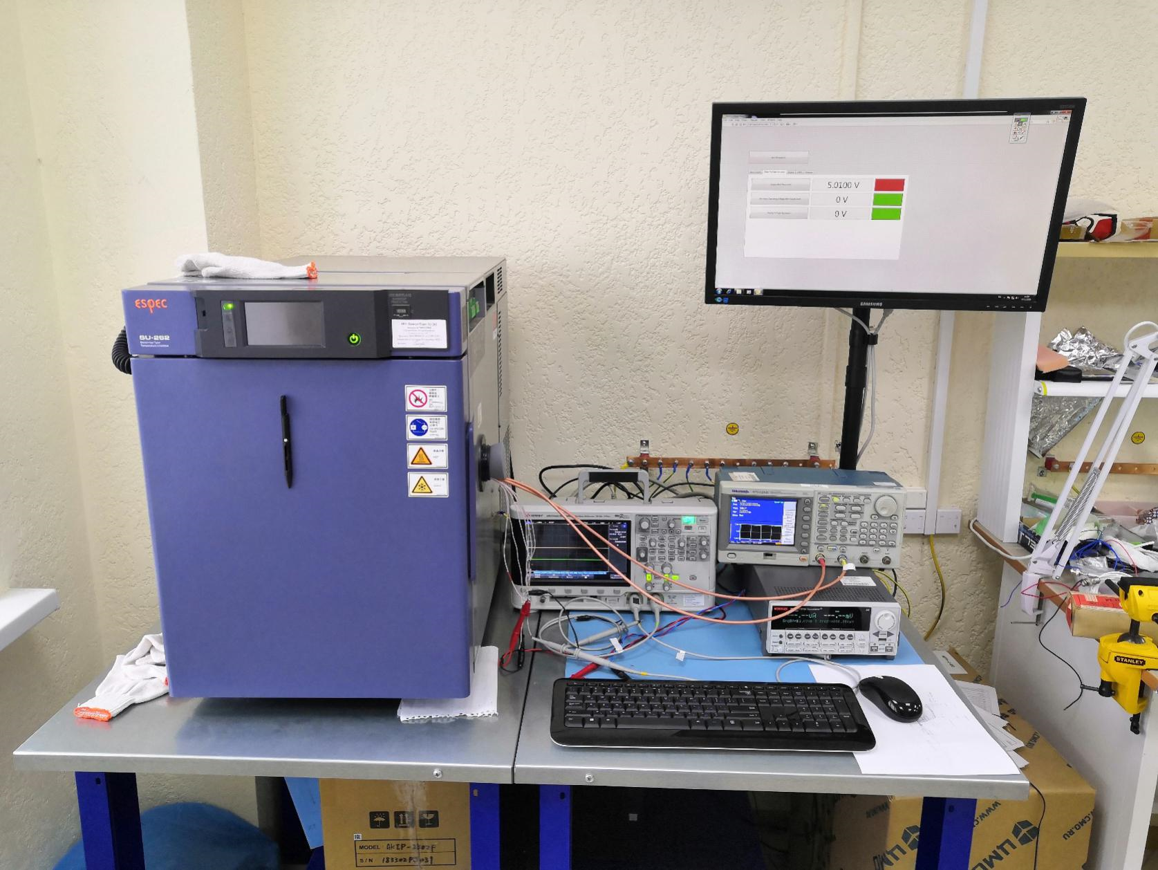
Heat and cold test chamber — exterior view
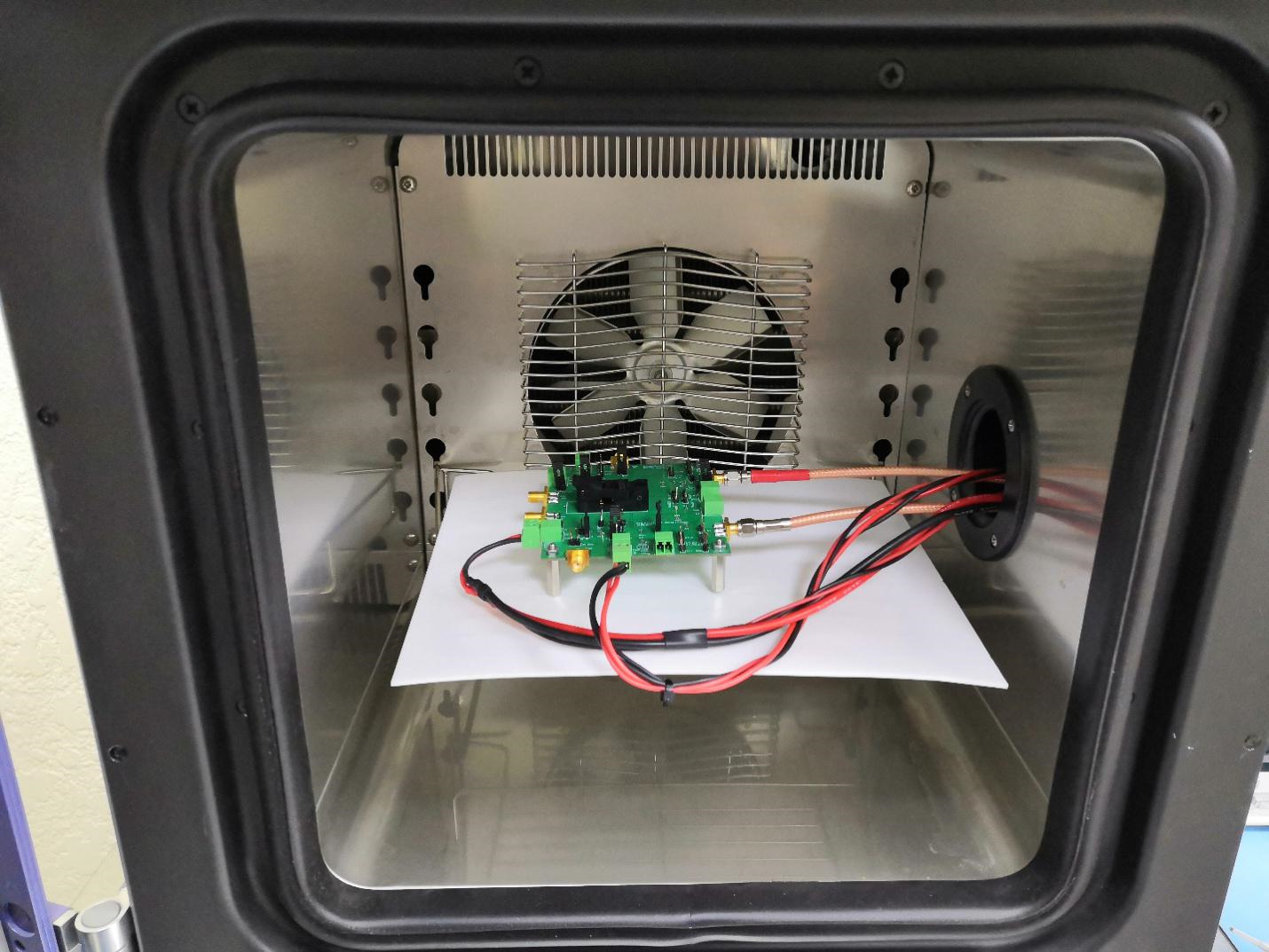
Heat and cold test chamber — interior view
In the process of measurements, you need to check the following: how much temperature margin does the die have in operating mode?
We connect the generator to the input of the microcircuit, and look at the output signal. With this test, the ambient temperature changes in the range of –60 ° C to 125 ° C. Thus, at the output of the transmitter, we see the following oscillogram:
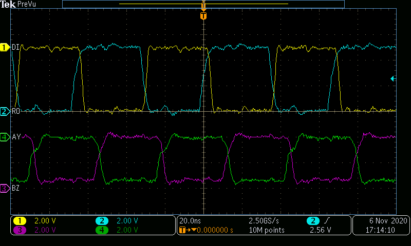
Oscillogram: DI — information input signal of the transmitter, AY, BY — output signals of the transmitter, RO — output signal of the receiver.
The circuit functioned normally over the entire temperature range. However, the question remains, what is the temperature margin? In order to answer this question, you need to understand what is the temperature of the die itself, outside the case. To measure the temperature of a die, we came up with a rather interesting approach that we can tell you about.
Almost all microcircuits have ESD protection (protection against electrostatic discharge). In the simplest case, it consists of 2 diodes used in reverse connection (one to ground, the other to power). Let us use the property that the physics of semiconductors is such that the voltage drop across a diode (pn junction) depends on temperature. We use the following connection scheme:

Here, we use the same heat and cold chamber. The task is as follows: to create the dependence of the voltage across the diode on temperature, which will help to calculate the temperature ratio. The measurement mode has being carried out with the circuit turned off, which excludes self-heating, thus, allows us to calibrate the scale:
- Power is not supplied to the microcircuit (VDD = 0)
- Connect a 10mkA current source to the DI digital pin
So, we get the following dependence:

The following value of the voltage temperature ratio was obtained: 1.78 mV / ° С.
Having calibrated the scale, you can proceed to assessing the heating of the microcircuit inside the plastic case in the operating mode under standard loads and in the event of a short circuit in the output stages. The measurement mode is as follows:
- supply voltage 5.5 V (VDD = 5.5 V)
- nRE pin — low level, DE pin — high level
- tested DI pin
- 10 µA diode current set on the source (Idiode = 10 µA)
- load — 54 Ohm
Probably, experts will say: why make it so difficult and why not simply apply a special test mode for measuring temperature to the circuit, but this approach allowed us to compare our microcircuit with the analogue MAX1478 (after all, for us it is a black box):
| Ambient temperature, °С | Temperature of a die, °С | |
| MDRI14853SI | MAX1478 | |
| 35 | 52,21 | 53,82 |
| 85 | 100,16 | 108,1 |
| 100 | 126,04 | 124,24 |
Conclusion-1: the die is heated up in operating mode by 26 ° C at an ambient temperature of 100 degrees. Thermal protection threshold (165 ºС) is still far away.
Conclusion-2: in the short-circuit mode, according to the available measurements, the thermal protection is triggered, already at 55 ºС of the ambient environment, but the microcircuit does not fail and after it cools down, it can function again.
Thus, we experimentally confirmed that the developed circuitry solutions reliably protect the microcircuit from abnormal situations (such as short circuit or drivers conflict) and does not affect the standard modes.
Conclusion
In this article, we tried to introduce readers with the features of such a popular interface as RS485. The development process for a microcircuit very closely interconnected with the measurement and prototyping processes. And here is the great merit of our application engineers, who let us know where mistake is made and what feature should be improved. And by doing this, proving the fact that the driver of any progress is constructive criticism.
