There is a list of well-known electronics design tools for Android which can be found in every review for the last 10 years: “Electrodoc”, “Every Circuit”, “Droid Tesla”, “Electronics Toolbox”, “RF & Microwave Toolbox” and so on. Also, there is a lot of trash on the market that turns finding a good tool into a quest.
This short review is about an unknown but cool tool “Circuit Calculator” working on Android devices and intended for professional electronics designers.
Routine tasks for electronics design engineers are:
Find a circuit template and customize it;
Circuit verification;
Repair a device. Sometimes it requires reverse of a circuit;
Compute some vales using basic equations;
Recall information about components, circuits, PCB routing, and standards.
A common device has an MPU, high-speed interfaces, an ADC and DAC with analog front-end. So, an engineer needs to design amplifiers, drivers, filters, power circuits, calculate PCB trace geometry to meet impedance and current requirements.
“Circuit Calculator” is intended to solve these tasks.
A current version includes more than 150 circuits for design and more than 50 calculators.
Nowadays most tools are online and require a large screen. "Circuit Calculator" works on small size Android devices and without the Internet.

After initial calculation, component values can be changed manually with automatic recalculation of other component values to match required parameters. A result can be shared as an HTML file with a circuit, bill of materials, input and output parameters.
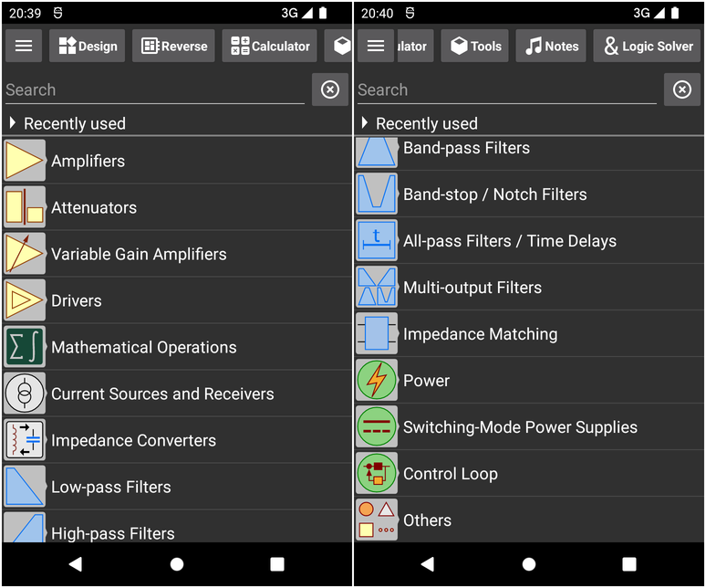
Amplifiers, attenuators, drivers
Inverting, Non-Inverting, Difference, Instrumentation amplifiers with operational and fully differential amplifiers.
Single-ended and differential variable gain amplifiers.
PI-, T-, Bridget-T attenuators, ladders.
Single-Ended, Differential, Balanced drivers including active termination.
For these circuits "Circuit Calculator" offers design, reverse, tuning and Monte-Carlo worst-case analysis. Noise evaluation can be done for common amplifiers.
An example of a non-inverting microphone amplifier is shown below. The input voltage is 10 mV, output voltage is 775 mV, and frequency range is from 300 Hz to 3500 Hz. The NE5532 parameters are used to evaluate output noise voltage.

Pay attention that you don't need to use a calculator to find a required gain, the equation is entered directly into the input field.
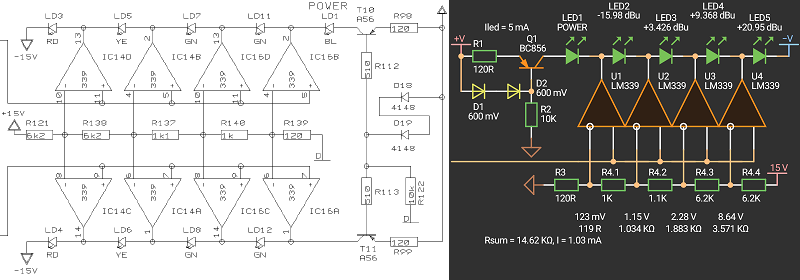
For repairing a device, the reverse option can be used. The pictures below show an LED level meter from a mixing console and its multi-tap resistor divider.

Range converting is often required to fit a signal voltage range to an ADC input voltage range. The picture below shows an example designed with “Circuit Calculator”. The input voltage range is from 2.5V to 3V and the output voltage range is from 0V to 3.3V.

Active termination drivers are used to reduce power losses. The picture below shows a differential driver for ADSL modems. The line impedance is 100 Ohm, and with a 1:1.5 output transformer the output impedance of the driver should be 44.44 Ohm.

Active and Passive Filters
Low-pass, High-pass, Band-pass, Band-stop LC ladders and Elliptic filters;
Low-pass, High-pass, Band-pass, Band-stop, All-pass, Multi-output filters with operational and fully differential amplifiers;
Along with common topologies, Multiple Feedback and Sallen-Key, the list includes also more complex topologies;
Tuning, reverse, Monte-Carlo worst-case analysis are supported.
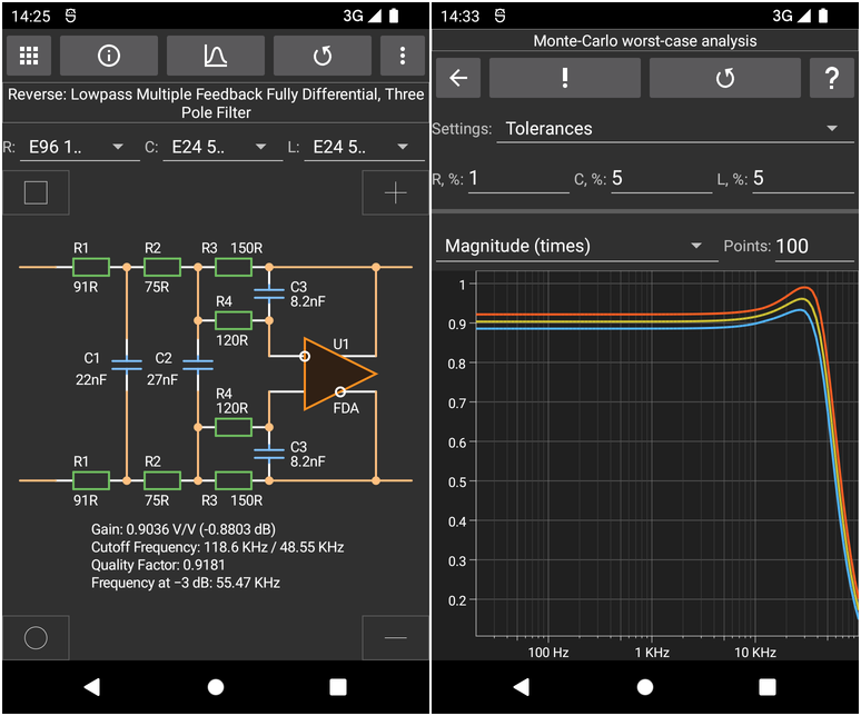
Reverse of a 3rd order low-pass filter from page 40 in the PCM1795 datasheet is shown in the picture.

Multistage active filters can be designed with a companion tool, “Filter Designer”.
Impedance matching
L-, PI-, T-networks in single-ended and differential configurations.

There are also tools for calculating trace impedance in various configurations. They are not as precise and flexible as in solvers like “Si9000” from Polar Instruments, but they cover basic needs.
Power circuits
The list includes basic switching-mode power supply modules: Buck, Boost, Inverting Buck-Boost, SEPIC, Ćuk, ZETA, Flyback, Forward, Half-Bridge, Push-Pull, Full-Bridge, Phase-Shifted Full-Bridge. Continuous Conduction Mode (CCM) is supported.
Voltage and current waveforms of components can be seen at different conditions without spending time for simulation. But of course they are idealized and without parasitics.
Control-to-output small-signal transfer functions are also computed allowing building a compensation network. Of course, the functions are simplified, but it is enough to start a design.
Type I, Type II, Type III compensation networks (PID) in different configurations.
There are also common circuits: feedback resistor divider, zener diode series resistor, damped LC filters, voltage multiplier.
The pictures below show a Push-Pull converter circuit from the LTC3723 SPICE simulation demo circuit and how it could be designed using “Circuit Calculator”.


The original circuit uses a Type III compensation network, but in fact a Type II can be used.
Tools
There is a large list of different tools. It includes common tools for working with component values, for power circuits, impedance calculators, PCB tools.

Logic circuits
A built-in logic solver tool is intended to convert a Veitch Map / Truth Table to a circuit and an equation.

Conclusion
“Circuit Calculator” is an electronics design tool covering a wide range of tasks. The tool is intended for electronics design engineers, and perhaps amateurs will find it too complicated.
It works on Android devices, even on old ones, has a small size, and does not require the Internet. Help contains information about circuits. It's like an interactive electronics engineer's pocket book.
The reverse option allows you to check a circuit and also find circuit design parameters that cannot be done with a simulator for circuits like filters.
Tuning and Monte-Carlo worst-case analysis reduce design time.
A result is a circuit with BOM and can be shared as an HTML file.
There is information about circuit ideas and templates, short info about components, standards, PCB routing rules.
Some circuits require a lot of input parameters and, unfortunately, the user interface is not very useful in such cases.
Tools like “Excel”, “Mathcad”, “Mathlab”, “Octave” and scripts in SPICE simulators are widely used. But it can be difficult to reuse the scripts if they are not well documented, with comments, input and output verification.
Vendor’s tools, like “WEBENCH” or “LTpowerCAD”, compute circuits with their IC. Of course, it will take more time if a side tool is used. But there are bugs in tools and mistakes in datasheets, so sometimes it's worth verifying calculations with third-party utilities. See, for example, a circuit on page 16 in the LT3723 datasheet. The compensation network has questionable parameters. Possible, there should be 4.7 nF capacitor instead of 0.47 uF.
Interestingly, the size of the tool is only about 2.5 MB. For comparison, sizes of programs are: TI’s “Analog Engineer Calc”: ~370 Mb; “Filter Pro”: ~11 Mb; “Power Stage Designer Tool”: ~2 Mb. AD’s “Diff Amp Calculator” ~2.5 Mb; LTpowerCAD: ~300 Mb. “Saturn PCB Toolkit”: ~12 Mb. However, they have the major advantage: they are free, unlike "Circuit Calculator" which costs money. It's up to you to decide if it’s worth using.