Introduction
Hi,
Currently I am investigating firmware development for STM32 microcontrollers and I would like to share with you my experience for doing it in Qt Creator IDE.
There are a lot of IDEs, which are used for firmware development of STM32. Some of them, being quite comfortable, have restrictions for trial license. For example, the one of the most known IDE, IAR Embedded, suggests either a limited amount of product usage time (30 days) or the limited firmware size of 32 MB, which is not too much.
Within this scope of the publication, we investigate the method of setting up an environment that allows developing the full value of the STM32 firmware in Qt Creator.
First, we need to determine the components for the execution of experiments.
Hardware
I use the bluepill board based on the STM32F103C8T6 microcontroller unit (MCU) to conduct the experiments. Sometimes, there could be issues with openocd, which claims the incorrect MCU number. It could be solved by 2 methods: either by replacing the number in the openocd configuration file or by changing the MCU to the original one. I chose the second option. For firmware burning and debugging purposes we use the ST-Link interface.
Software
The experiments are conducted on a Windows 10 virtual machine in Virtual Box. In addition, we will need to install the following software:
Qt Creator. It could be installed with the online installer package from the Qt website. In this case, registration is required, and we do not need the Qt framework itself. For this reason, I download Qt Creator directly from the GitHub releases: https://github.com/qt-creator/qt-creator/tags.
gcc-arm-none-eabi. https://developer.arm.com/downloads/-/gnu-rm.
Git. https://git-scm.com/downloads.
openocd. https://github.com/openocd-org/openocd/tags. This software is designed for firmware burning and on-chip firmware debugging .
make. https://gnuwin32.sourceforge.net/packages/make.htm
ST-LINK Utility. This utility is used for firmware burning and also contains a USB driver for ST-Link interface. https://www.st.com/en/development-tools/stsw-link004.html
Python2.7. https://www.python.org/downloads/release/python-2718/
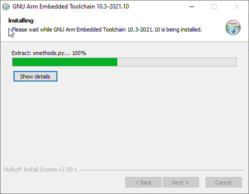
First, we need to download and unpack Qt Creator, and after that to install git, gcc compiler, openocd, python, make and ST-Link utility.
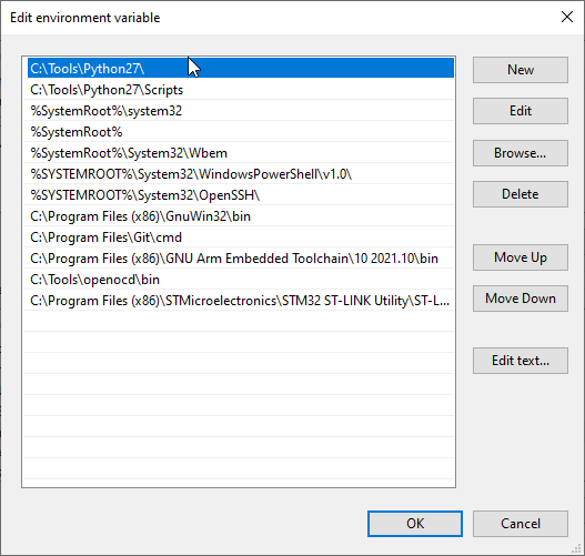
I unpacked Qt Creator and openocd into C:\Tools. All programs, except Qt Creator, should be added to Path.
Then we need to check whether gcc and openocd are pushed to Path by calling them from the command line.
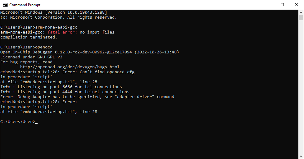
If gcc and openocd are available from cmd, we can move forward and tune the Qt Creator IDE.
Setup of Qt Creator
Now we can launch the IDE and install the necessary plugins: BareMetal and GenericProjectManager. To do this we need to go to Help->About Plugins, check the plugins and restart Qt Creator.

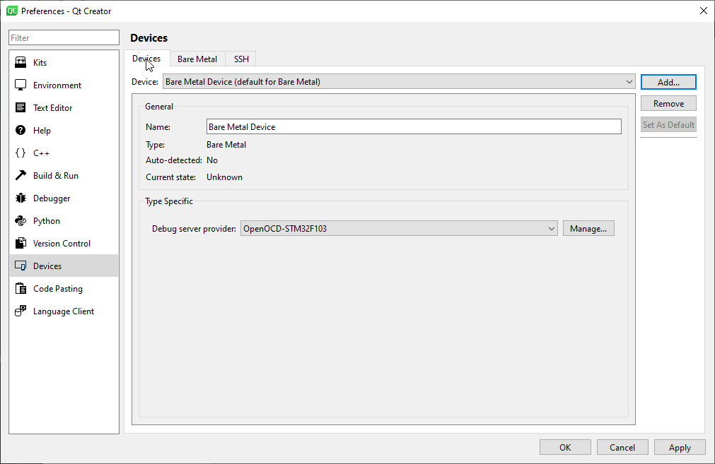
The first thing we need to do is to go to Edit->Preferences and choose Kits from the list on left. Here we should see our kit for building an ARM, which was pulled from Path. Next, we go to Devices from the list on the left, on the Bare Metal tab, and add an OpenOCD server. In our case, I call it OpenOCD-STM32F103.

In Executable file we write the path to openocd (theoretically could be taken from Path).
In the Root scripts directory we point the script directory for openocd.
In Additional arguments we write the arguments for burning of firmware to MCU: config file for ST-Link and our target: stm32f1x. Then apply.
Go to Devices. Click Add->Bare Metal Device and Start Wizard. In the appeared window we choose Debug server provider and previously added OpenOCD-STM32F103 server provider. Click Finish.
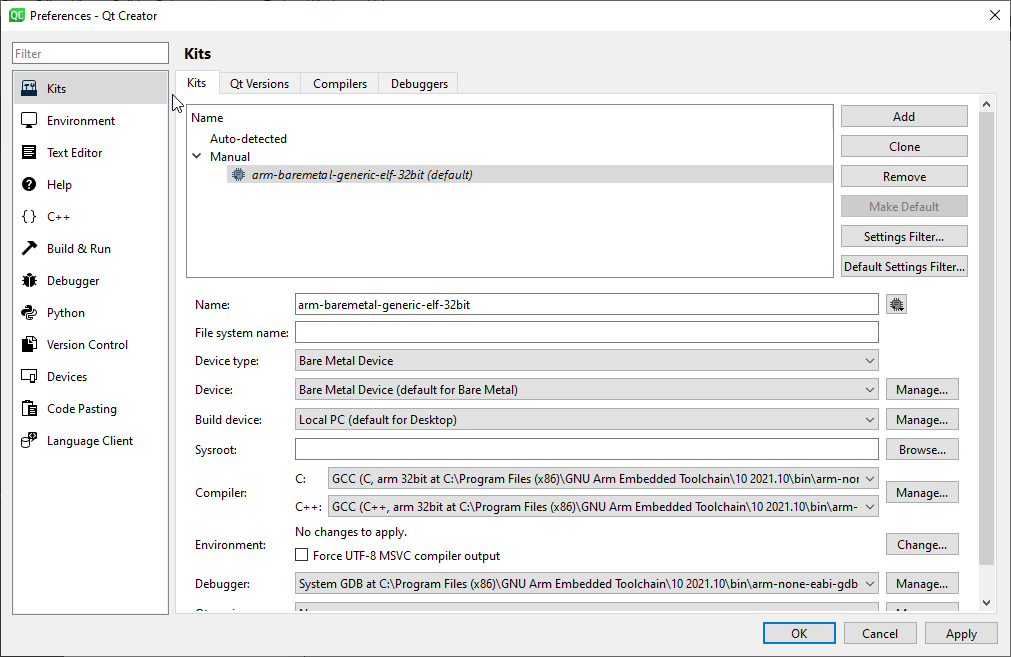
Return to Kits and readjust our ARM kit. We need to choose previously configured Device type and Device – Bar Metal Device. Apply.
At this stage we postpone Qt Creator and move to setup of the project.
Setup of project
We will create the simplest project using only CMSIS library which will blink with LED.
First, we need to pull the necessary libraries as the submodules from the official repositories of ARM and ST. Open bash terminal, which usually goes together with git, and create led_blink_cmsis folder.
mkdir led_blink_cmsis && cd led_blink_cmsisCreate inside build, lib and src folders.
mkdir build && mkdir src && mkdir libIn the build folder we have the artifacts, in src - our source files and in lib - third party libraries.
Initialize git.
git initNext, add CMSIS libraries using git submodules. The first library is the ST fork from the ARM repo. The second has the settings and definitions for the STM32 F1 family.
git submodule add https://github.com/STMicroelectronics/cmsis_core lib/cmsis_core && cd lib/cmsis_core
git checkout v5.6.0 && cd ../..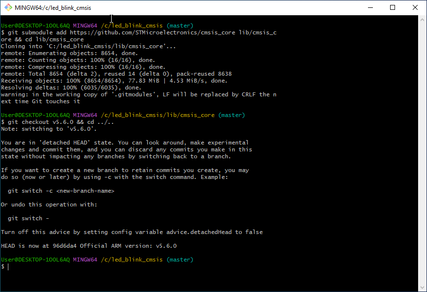
git submodule add https://github.com/STMicroelectronics/cmsis_device_f1 lib/cmsis_device_f1 && cd lib/cmsis_device_f1
git checkout v4.3.3 && cd ../..
After adding submodules we make git checkout to release versions of libraries. For cmsis_core and cmsis_device the current versions are correspondingly 5.6.0 and 4.3.3 .
Create main.c, init.h and init.c in the src directory, which contain our source code.
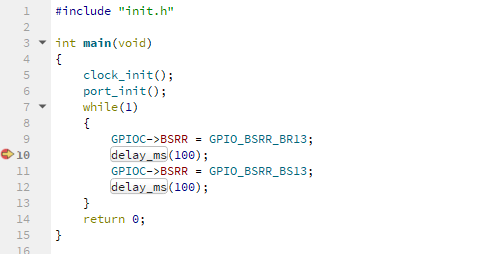
touch src/main.c src/init.h src/init.cLet us fill our files with code. In main.c there is a code which turns on and off the LED as well as calls the clock_init и port_init functions. These functions set up the clock frequency and external clocking from the quartz resonator as well the functioning of port C for output in low frequency push-pull mode. The init.c file also contains the implementation of the delay_ms function .
main.c
#include "init.h"
int main(void)
{
clock_init();                                                //Clock initialization
port_init();                                                 //Port initialization
while(1)
{
GPIOC->BSRR = GPIO_BSRR_BR13;                            //Pin 13 of PORT C on
delay_ms(100);
GPIOC->BSRR = GPIO_BSRR_BS13;                            //Pin 13 of PORT C off
delay_ms(100);
}
return 0;
}
init.h
#ifndef STM32F103xB
#define STM32F103xB
#endif
#include "stm32f1xx.h"
int clock_init();
void port_init();
void delay_ms(uint16_t);
init.c
#include "init.h"
volatile uint32_t SysTickDelayMsec = 0;
void SysTick_Handler(void)
{
--SysTickDelayMsec;
}
/*
OSC - 8 MHz
PLLSRC - 8 MHz
SYSCLK - 16 MHz
PLL - 2
AHB - 1/16
*/
int clock_init()
{
RCC->CR |= RCC_CR_HSEON;                                    //Start HSE generator
for(volatile int StartUpCounter = 0; ; ++StartUpCounter)    //Wait for successfull start or timeout
{
if(RCC->CR & RCC_CR_HSERDY)                             //If started successfully, break the cycle
{
break;
}
if(StartUpCounter > 4096)                               //If not started - turn off and return an error
{
RCC->CR &= ~RCC_CR_HSEON;                           //Stop HSE
return 1;
}
}
RCC->CFGR = 0;                                              //PLL mult is equal 2
RCC->CFGR |= RCC_CFGR_PLLSRC;                               //Clock PLL from HSE
RCC->CR |= RCC_CR_PLLON;                                    //Start PLL
for(volatile int StartUpCounter = 0; ; ++StartUpCounter)    //Wait for successfull start or timeout
{
if(RCC->CR & RCC_CR_PLLRDY)                             //If started successfully, break the cycle
{
break;
}
if(StartUpCounter > 4096)                               //If PLL didn't start , turn off everything and return an error
{
RCC->CR &= ~RCC_CR_HSEON;                           //Stop HSE
RCC->CR &= ~RCC_CR_PLLON;                           //Stop PLL
return 2;
}
}
FLASH->ACR |= FLASH_ACR_LATENCY;                            //0 cycles for flash, core clock 16 MHz
RCC->CFGR |= RCC_CFGR_PPRE2;                                //APB2 turned off (0 by default)
RCC->CFGR |= RCC_CFGR_HPRE_3 |
RCC_CFGR_HPRE_1 |
RCC_CFGR_HPRE_0;                               //AHB prescaler 16
RCC->CFGR |= RCC_CFGR_SW_1;                                 //Switch to PLL
while((RCC->CFGR & RCC_CFGR_SWS) != RCC_CFGR_SWS_PLL);      //Wait for switch to PLL
RCC->CR &= ~RCC_CR_HSION;                                   //Turn off the internal clock for energy save
SystemCoreClockUpdate();                                    //Apply alterations to generator
SysTick_Config(SystemCoreClock/1000);                       //Initialisation of interrupt (1 ms)
return 0;                                                   //Return 0 if success
}
void port_init()
{
RCC->APB2ENR |= RCC_APB2ENR_IOPCEN;                         //Turn on clock for GPIOC
GPIOC->CRH = 0;
GPIOC->CRH |= GPIO_CRH_MODE13;                              //Pin 13 of PORT C in Push-Pull mode
GPIOC->BSRR |= GPIO_BSRR_BR13;                              //Pin 13 of PORT C reset
}
void delay_ms(uint16_t msec)                                     //Delay function
{
SysTickDelayMsec = msec;
while (SysTickDelayMsec);
}
Finally, we add the Makefile, which is used for building of firmware. The template of the file was taken from MXCube generator and adapted for the current project. It contains the following code.
Makefile
######################################
target
######################################
TARGET = mppt_firmware
######################################
building variables
######################################
DEBUG = 1
OPT = -O0
#######################################
paths
#######################################
BUILD_DIR = build
######################################
source
######################################
C_SOURCES =
src/main.c
src/init.c
lib/cmsis_device_f1/Source/Templates/system_stm32f1xx.c
ASM_SOURCES =
lib/cmsis_device_f1/Source/Templates/gcc/startup_stm32f103xb.s
#######################################
binaries
#######################################
PREFIX = arm-none-eabi-
ifdef GCC_PATH
CC = (PREFIX)gcc
AS = (PREFIX)gcc -x assembler-with-cpp
CP = (PREFIX)objcopy
SZ = (PREFIX)size
else
CC = $(PREFIX)gcc
AS = $(PREFIX)gcc -x assembler-with-cpp
CP = $(PREFIX)objcopy
SZ = $(PREFIX)size
endif
HEX = $(CP) -O ihex
BIN = $(CP) -O binary -S
#######################################
CFLAGS
#######################################
CPU = -mcpu=cortex-m3
MCU = $(CPU) -mthumb $(FPU) $(FLOAT-ABI)
AS_DEFS =
C_DEFS =
-DSTM32F103xB
AS_INCLUDES =
C_INCLUDES =
-Isrc
-Ilib/cmsis_core/Include
-Ilib/cmsis_device_f1/Include
ASFLAGS = $(MCU) $(AS_DEFS) $(AS_INCLUDES) $(OPT) -Wall -fdata-sections -ffunction-sections
CFLAGS = $(MCU) $(C_DEFS) $(C_INCLUDES) $(OPT) -Wall -fdata-sections -ffunction-sections
ifeq ($(DEBUG), 1)
CFLAGS += -g -gdwarf-2
endif
CFLAGS += -MMD -MP -MF"$(@:%.o=%.d)"
#######################################
LDFLAGS
#######################################
LDSCRIPT = lib/cmsis_device_f1/Source/Templates/gcc/linker/STM32F103XB_FLASH.ld
LIBS = -lc -lm -lnosys
LIBDIR =
LDFLAGS = (LDSCRIPT) (BUILD_DIR)/$(TARGET).map,--cref -Wl,--gc-sections
#######################################
build the application
#######################################
all: (TARGET).elf (TARGET).hex (TARGET).bin
OBJECTS = (notdir $(C_SOURCES:.c=.o)))
vpath %.c $(sort $(dir $(C_SOURCES)))
OBJECTS += (notdir $(ASM_SOURCES:.s=.o)))
vpath %.s $(sort $(dir $(ASM_SOURCES)))
(BUILD_DIR)/$(notdir $(<:.c=.lst)) $< -o $@
$(BUILD_DIR)/%.o: %.s Makefile | $(BUILD_DIR)
$(AS) -c $(CFLAGS) $< -o $@
(TARGET).elf: $(OBJECTS) Makefile
$(CC) $(OBJECTS) $(LDFLAGS) -o $@
$(SZ) $@
$(BUILD_DIR)/%.hex: $(BUILD_DIR)/%.elf | $(BUILD_DIR)
$(BIN) $< $@
$(BUILD_DIR)/%.bin: $(BUILD_DIR)/%.elf | $(BUILD_DIR)
$(BIN) $< $@
$(BUILD_DIR):
mkdir $@
clean_build: (TARGET).elf (TARGET).bin
find (TARGET).bin' -type f -exec rm -f {} +
#######################################
clean up
#######################################
clean:
rm -fR $(BUILD_DIR)/*
C_INCLUDES shows the path to .h files.
C_SOURCES shows the path to .c/.cpp.
DEBUG indicates the addition of debug symbols to firmware. In release version it should be 0.
OPT indicates the optimization level. For release it should be, for example, Os.
Instead of Makefile any other build system could be used. As an example, I can suggest CMake with the corresponding toolchain file for STM32.
Add the build folder to.gitignore to exclude its contents from git tracking.
echo build/* > .gitignoreAt this stage the project is set up, and it could be imported to Qt Creator.
Import and setup of the project in Qt Creator
Qt Creator is not very good with Makefile. If we try to use Autotools plugin, we will see only .c and .cpp files. For this reason, we import the project with a special interface from the GenericProjectManager plugin.
Go to File->New Project and to Import Existing Project on the left.
Name the project led_blink_cmsis and set the path to C:\led_blink_cmsis. Next.
Show which files should be imported. Currently we choose the src folder only. Next.

Choose add to version control – none and click Finish. The files have been imported now.
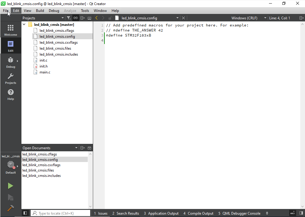
Go to the project explorer and add to led_blink_cmsis.config the definition of our MCU, #define STM32F103xB. The IDE autocompletion does not work without this definition because it is required to define the MCU type for CMSIS to include the necessary parts of code for project build.
At this stage Qt Creator does not recognize our src files. Let us fix it.
Add .c files to led_blink_cmsis.files
src/init.c
src/main.c
In led_blink_cmsis.inludes we need to set the path to .h files.
src/
lib/cmsis_core/Include
lib/cmsis_device_f1/Include
Now everything should be displayed correctly.

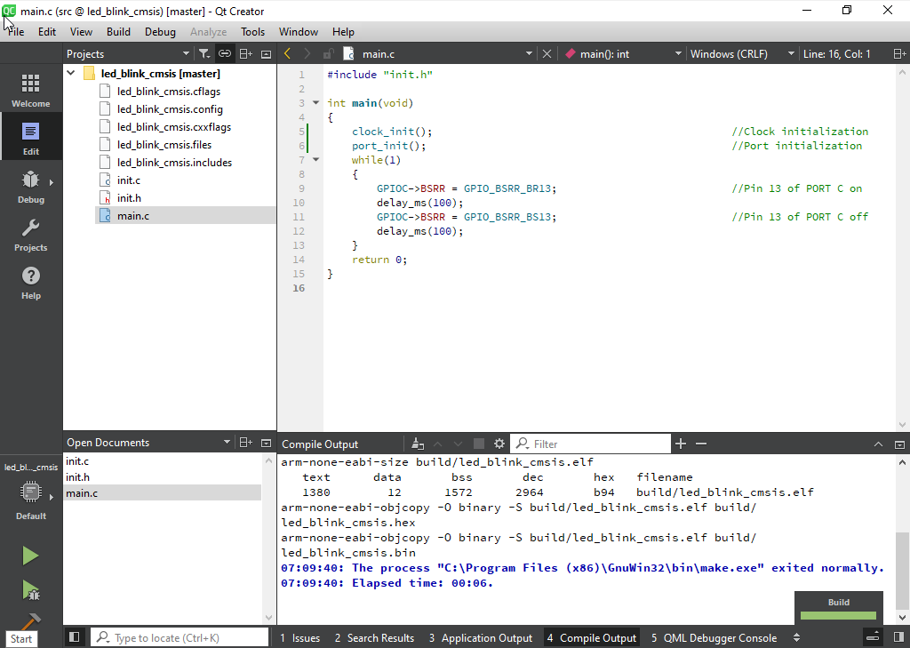
Try to compile the project by clicking on the Build button. The project should compile, and at the end of the output we will see a table with the size of the firmware.
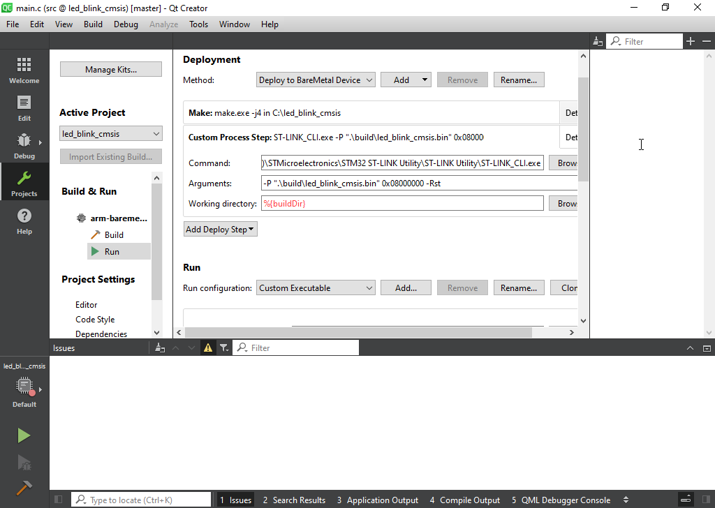
Let us add the autodeploy of our firmware by clicking the Run button. Go to Projects on the left, choose our kit arm-baremetal-generic-elf-32bi and after Run on the bottom. On the right, in the deployment section, Add Deploy Step->Make. Repeat the step, choosing the Custom Process Step, and add the command to burn the MCU with ST_link CLI.
C:\Program Files (x86)\STMicroelectronics\STM32 ST-LINK Utility\ST-LINK Utility\ST-LINK_CLI.exe
-P ".\build\led_blink_cmsis.bin" 0x08000000 –Rst
Before burning of MCU connect ST-Link with MCU and PC. We burn the MCU starting from the 0x08000000 segment and reboot the MCU after burning.
Now, if we connect the MCU with ST-Link and click the Run button, the firmware should be compiled, loaded to the MCU. The LED on PC13 should start to blink, which we can see on the oscilloscope.

In this section we considered how to set up the project for STM32, to compile it and load into MCU. The next section is devoted to the setup of a debugger for comfortable STM32 debugging.
Setup of debugging
Previously we have already set the remove debugging using openocd, and it should work.
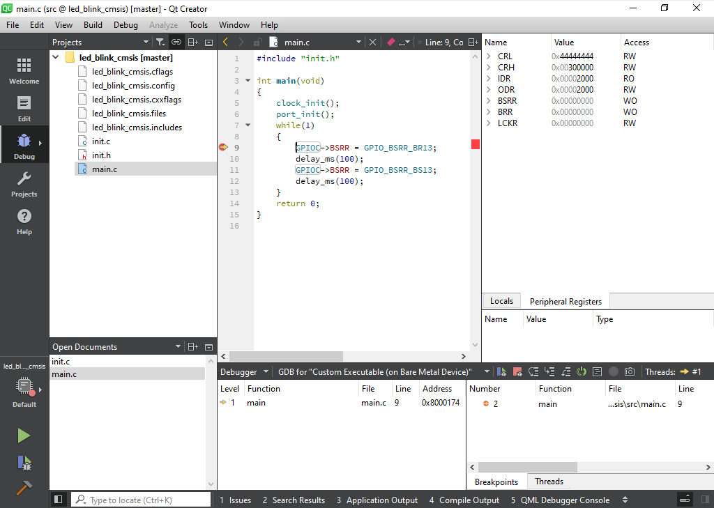
However, it is quite good to have the possibility to see the current status of MCU registers. Let us add such a possibility. To do this we need .svd file for our MCU, STM32F103. I could be downloaded, for example, from this repo:
Next, go to QtCreator Edit->Preferences->Devices, to Bar Metal tab and choose the OpenOCD. Put to Peripheral description file field our path to .svd file.
During run-time debug go to View->Views and enable PeripheralRegisters. Launching the debug window on the right and clicking the right mouse button at the Peripheral Registers window, we can choose a group of registers for display. For example, View Groups->GPIOC.
Finally, we have setup all the necessary features for comfortable development and debugging of STM32 firmware in Qt Creator IDE.
Conclusion
Within the scope of the article we convinced the setup of Qt Creator IDE with GNU compilers for full-fledged development of software for STM32 MCU. I hope the article was interesting and useful.
Thanks for your attention!
