Pull to refresh
1
@servosilaread⁠-⁠only

Robotics & Artificial Intelligence

Send message

Making an Encoder Cable for Servosila Brushless Motor Controller. Testing in Direct Drive mode

Reading time2 min
Views874

In this video, we are making a cable for connecting a quadrature encoder to a Servosila brushless motor controller, and and then running a servo motor in Direct Drive mode. To make the cable we are using a cable assembly kit that can be purchased from the internet store. Alternatively, the components for the cable can be bought in other places. The part numbers are given in the controller's datasheet.

The cable assembly kit consists of a connector and a set of wires with pre-crimped socket blades. If you have a crimper tool, you can also attach the socket blades to wires by yourself.

Lets open a datasheet document that comes with the brushless motor controller. Note that each connector has its first pin clearly marked with a "1" sign. Conventionally, the numbering of pins is done in such a way that there are rows of odd-numbered and even-numbered pins.

The quadrature encoder's electrical interface has 5 wires in total. Positions of the pins of each of the wires are given in the table. The socket blades need to be pushed into the connector until you feel a "click". The blades lock into the connector's sockets. Optionally, primarily for cosmetic reasons, you may want to add a heat-shrink tubing to your cable.

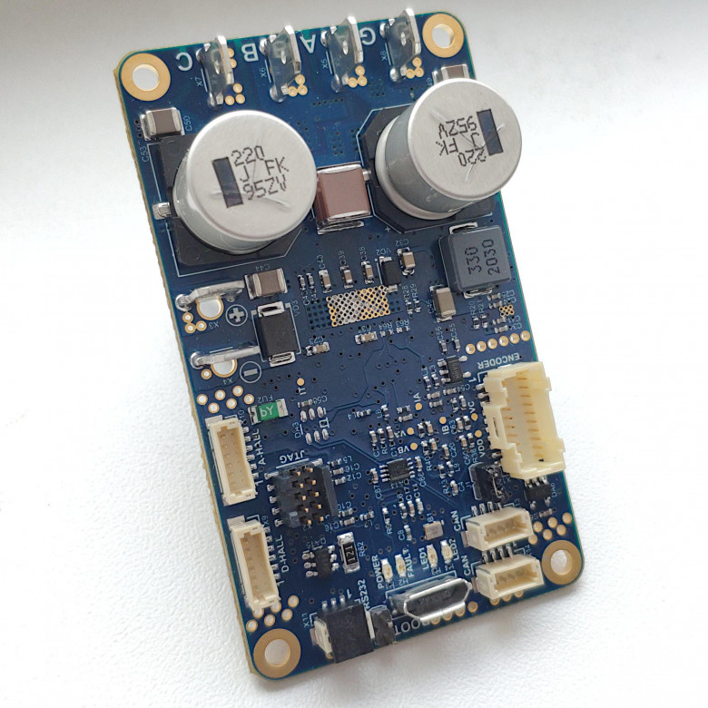
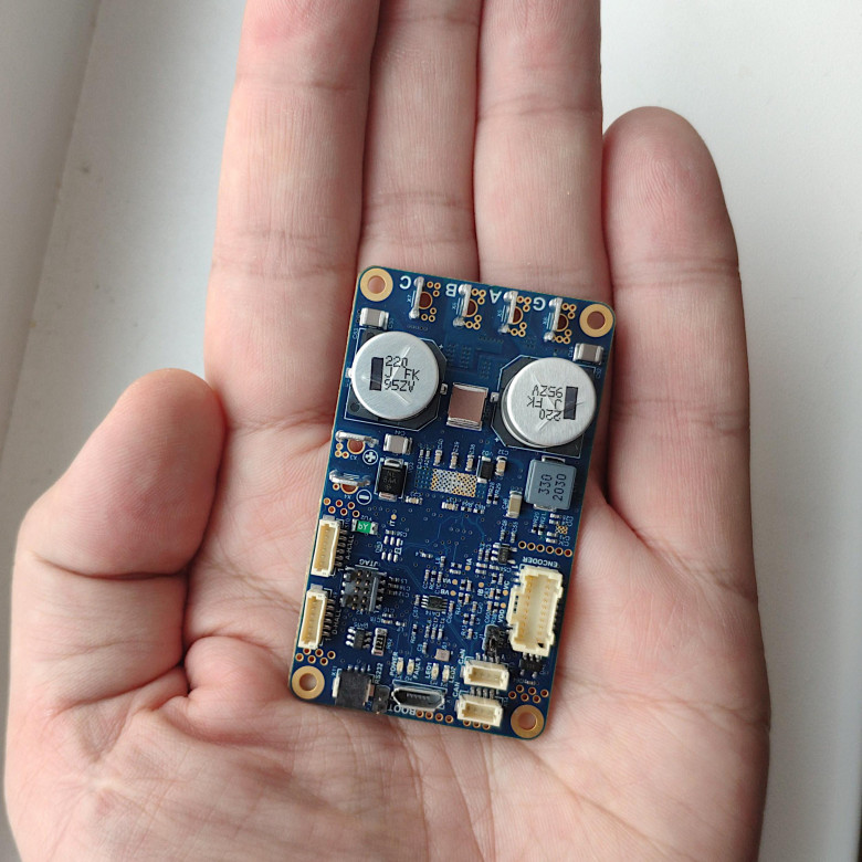
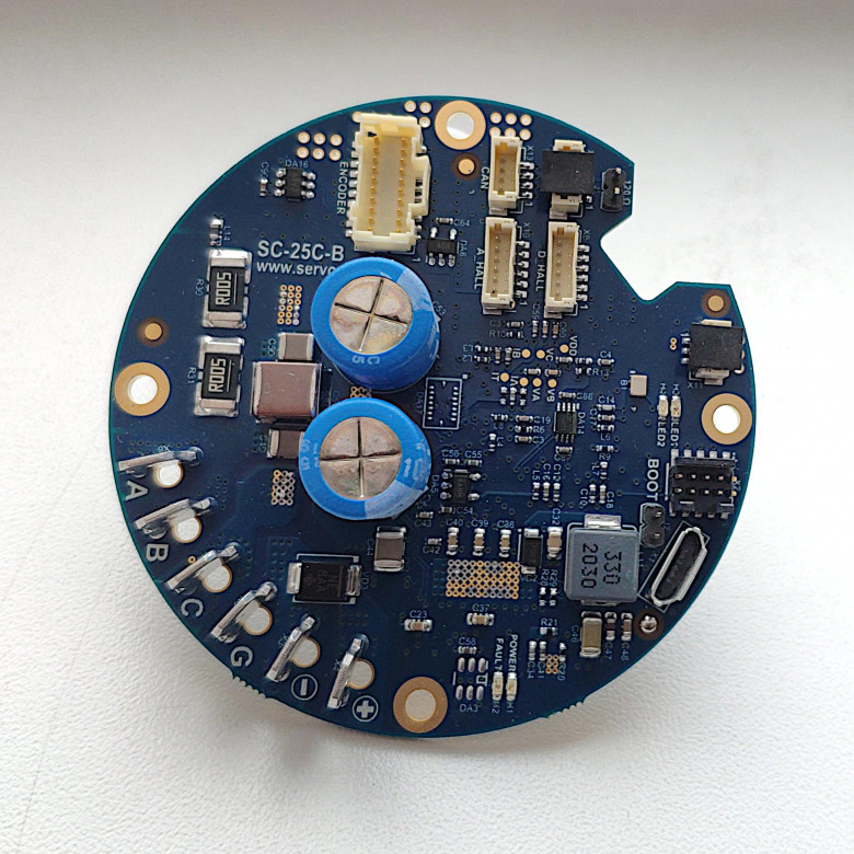
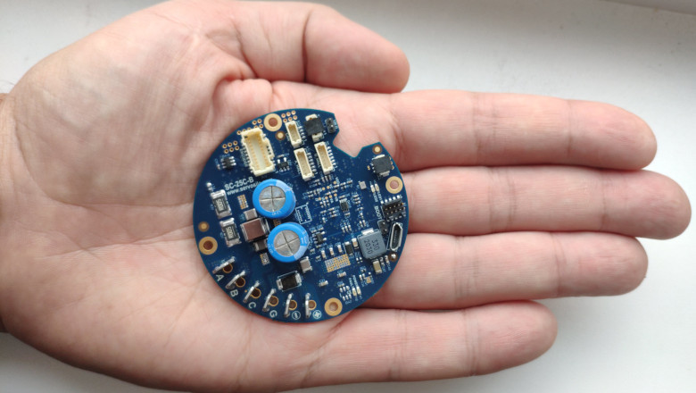
The brushless motor controllers come in two distinct forms, a circular and a rectangular one. Both models are identical in terms of capabilities, features, firmware, and external electrical connectors.

The connector has a locking mechanism that keeps it in place. I soldered a mating connector to the other side of the cable - a connector that my brushless motor needs. Note that your motor will likely require a different connector, or no connector at all. It is always a good idea to test an end-to-end integrity of the cable and its connectors. Lets buzz the wires using a multimeter. The cable is ready.

Video & Read more
Total votes 5: ↑3 and ↓2+1
Comments0

Controlling Brushless Motors using a Linux computer or a PLC

Reading time5 min
Views2.6K

In this video, we will look at how to connect brushless motor controllers to a Linux computer. Specifically, we will use a computer running Debian. The same steps would work for Ubuntu Linux and other Linux distributions derived from Debian.

I've got a small sensorless brushless motor, and a bigger brushless motor with a built-in absolute encoder. Lets look at how to control those from my Debian Linux computer. Servosila brushless motor controllers come in several form factors with either a circular or a rectangular shape. The controllers come with a set of connectors for motors and encoders as well as for USB or CANbus networks.

The controllers can be powered by a power supply unit or by a battery. To spice up my setup, I am going to use a battery to power the controllers and thus their motors. The controllers need 7 to 60 volts DC of voltage input. If I connect the battery, the controllers get powered up. The small LED lights tells us that the controllers are happy with the power supply.

We need to connect the brushless motor controllers to the Linux computer. There are two ways to do that - via CANbus or via USB. Lets look at the USB option first. A regular USB cable is used. Only one of the controllers needs to be connected to a computer or a PLC.

Next, we need to build an internal CANbus network between the controllers. We are going to use a CANbus cross-cable to interconnect the controllers. Each controller comes with two identical CANbus ports that help chain multiple controllers together in a network. If one of the interconnected brushless motor controllers is connected to a computer via USB, then that particular controller becomes a USB-to-CANbus gateway for the rest of the network. Up to 16 controllers can be connected this way via a single USB cable to the same control computer or a PLC. The limit is due to finite throughput of the USB interface.

Video & Read more
Total votes 4: ↑3 and ↓1+2
Comments0

Controlling Brushless Motors from Windows

Reading time4 min
Views1.4K

In this video, we will look at how to connect brushless motors to a Windows computer via USB. We are going to connect a network of Servosila brushless motor controllers to the computer. The other option is CANbus interface, but we will look at CANbus in a dedicated video. A regular USB cable is used. Note that the USB cable is not used to power the controller and its motor.

The first brushless motor controller in network appears to Windows as a Virtual COM port. Once connected via USB, it can be found in a general list of devices in the Window's "Settings" window. Up to 16 controllers can be connected this way via a single USB cable to the same control computer or a PLC. If one of the interconnected brushless motor controllers is connected to a computer via USB, then that particular controller becomes a USB-to-CANbus gateway for the rest of the network.

If your computer happens to have more that one serial port, you may wish to check a COM port's number assigned by Windows to the controller. Then, you pick this COM port in a drop down menu in the Servoscope software, and click Connect. If the COM port is not listed in the drop-down menu, click the Refresh button. If everything is good, the controller appears in a list of devices. Double-click to open up a control and configuration window.

Video & Read more
Total votes 5: ↑3 and ↓2+1
Comments0

Controlling Brushless Motors using Raspberry PI

Reading time5 min
Views3.3K

In this video tutorial, we will control a pair of brushless motors from a Raspberry PI computer. We will use one of the computer's USB ports to connect a network of brushless motor controllers. We will power the computer, the controllers, and the brushless motors using a single battery, similar to a autonomous vehicle design.

The first motor is an outrunner type, a kind of what you would use for a vehicle propulsion. The bigger motor comes with a quadrature encoder which means it can be used as a powerful servo.

I made a cable to power my set up. On one end, the cable has a socket for plugging the battery. The cable splits into a two parallel parts to power the controllers, and the Raspberry PI. The bottom part of the cable further splits to power a pair of brushless motor controllers.
By the way, the controllers need 7 to 60 Volts DC. I put proper connectors at the ends of the cable, so that I could just plug it into the controllers.

Servosila brushless motor controllers come in rectangular or circular form factors. The controllers have USB and CANbus ports for connecting to control computers such as Raspberry PI.

Video & Read More
Total votes 6: ↑5 and ↓1+4
Comments0

Управление бесколлекторными двигателями из Astra Linux

Reading time3 min
Views4.7K

В этом видео мы подключим бесколлекторные двигатели к компьютеру с операционной системой Astra Linux, настроим нужное программное обеспечение, и поймем общую схему работы с двигателями, а также с абсолютными энкодерами положения вала.

Astra Linux - это российский дистрибутив Линукс, который сертифицирован для специальных применений. В этом видео мы будем использовать версию Орел, Common Edition с hardened ядром.

Для сборки стенда будем использоваться бесколлекторный двигатель со встроенными датчиками Холла и встроенным квадратурным энкодером. Также есть небольшой бездатчиковый бесколлекторный двигатель и магнитный абсолютный энкодер положения вала.

Для подключения двигателей и энкодеров к компьютеру с Astra Linux будем использовать контроллеры бесколлекторных двигателей компании Сервосила. Контроллеры бывают прямоугольной или круглой формы. На контроллерах есть разъемы для подключения двигателей, энкодеров, датчиков Холла и питания.

Контроллерам двигателей требуется напряжение питания от 7 до 60 вольт DC. Я приспособил блок питания от старого ноутбука. Блок питания выдает напряжение 19.7 вольт. Я раздвоил кабель и плоскогубцами закрепил разъемы для подключения кабелей к контроллерам.

Сборку начнем с шин данных USB и CANbus. Обыкновенный кабель USB используется для подключения одного из контроллеров к управляющему компьютеру или PLC. Остальные же контроллеры подключаются друг к другу гирляндой с помощью кабелей шины CANbus. Тот единственный контроллер, который подключен по USB к комьютеру, становится шлюзом USB-в-CANbus для всех остальных контроллеров в цепочке.

Читать далее
Total votes 16: ↑7 and ↓9-2
Comments6

Information

Rating
Does not participate
Registered
Activity